This week, we started on Project 1: Design and build a laminated form that rhymes with a location on campus. Our goal is to build four different small-scale models in at least two different materials. My project partner is Julie Harris, please refer to her blog for more references and ideas. https://julieludigitaldesign.wordpress.com/
Inspiration:
For our first large project, we (Julie Harris and Wendy Wu) designed
models for laminated forms that rhyme with places on campus. We decided
to focus on four different parts of campus: domes, paths, beehives, and
the Crum Creek.
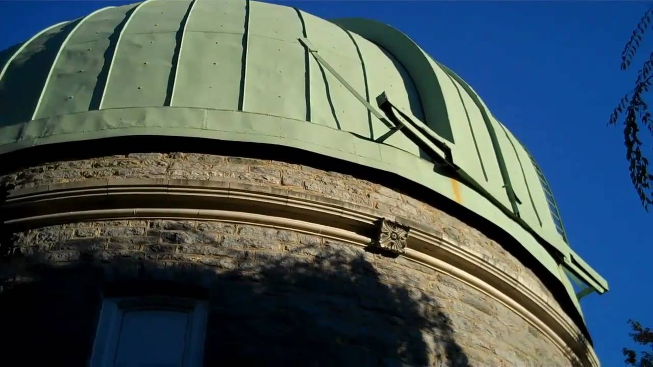
The first form, based around the the many domes on campus, mirrors
the visual of seeing domes next to each other in the distance. We
designed a set of four domes, each decreasing in size. The three
smaller domes have slivers cut out of them so they rest comfortably next
to the larger ones, as though they’re connected to each other.
Original model drawing
To create this, we drew out a series of half-dome cross-sections (see
above image), and used these to determine the radius of each circular
level. Then, we decided how far apart the domes should be, and used
this distance to figure out how much of each circle should be cut out.
Half-dome cross-section sketchesCircles drawn on foam board, ready to be cut out
With the final product, each dome is its own solid object,
disconnected from each other dome. This gives us freedom in how we
arrange the domes, so they might be in a line, or a grouping. We made
the models out of foam board, because it works well with curved forms.
Final model, in a lineFinal model, grouped
The next model we designed was based on the curving paths around
campus. We were interested photos we saw online, where the angle and
foreshortening really emphasized the curves. We wanted to put even more
emphasis on this by having our model look like the foreshortened image
from above, so that the effect was even more extreme when looking at it
from an angle. We also wanted to bring a three-dimensional element into
the curve, by having the path curve up on one side at the front, then
move to curve up on the other side at the back.
Original model drawing
In order to make this as a laminated form, we would build up each
layer of the path with smaller and smaller pieces of material. The left
side of the above image shows each cross-section along the path. The
right side shows the path outline, and where the layers would appear.
We decided to make this model out of balsa wood, since it works well for long, straight lines.
Path model top viewPath model side view, showing height differences
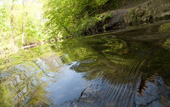
For the next model, we were interested in the creek running by
campus. As the water moves through the creek, it changes shape. To
represent this, we decided to design a hollow curved shape that would
change slightly each time it was repeated. This would give us a
dynamic hollow structure that extends outward on one ends and inward on
the other, representing the unpredictability and fluidity of the water.
We planned to carry it out on Illustrator and laser cut on stained teal
glass in order to maximize the effect of airiness and transparency.
Water model original drawingWater model side view Water model top view
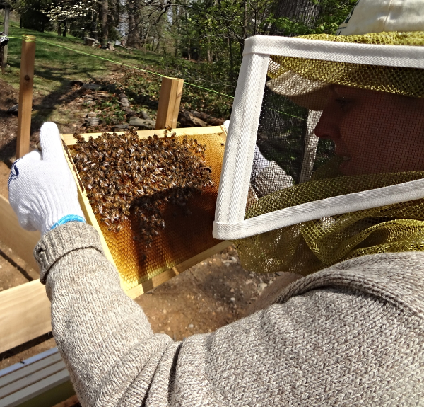
Finally, our last model was drawn from the flourishing greens and
beehives on campus. The cross section of a leaf would show porous canals
for nutrient and O2 transportation, and we planned to combine it with
the intricate shapes of beehive hexagons. We drew the plan of Adobe
Illustrator, which contained 12 layers of drawing — one for the beehive
base, and each one layers up like a topography image. However, when we
transfered the .ai file to Papazian desktop for laser cutting, the
computer failed to completely transfer the beehive model. So, we only
made a model of the porous canals. If we end up using this model in our
final design, this technical problem can be simply solved by creating a
pattern out of hexagons and overlap it as a layer.
Preliminary sketches:
Process:
Beehive model in progress.
Chlorophyl model top viewLighting entering layers of Chlorophyl canal


 Beehive model in progress.


Comments
Post a Comment